Airbus prepares for its first megawatt-class hydrogen fuel-cell engine flight-test demonstrator
Hydrogen-powered fuel-cell engine architecture with cryogenic storage could feature in an all-new zero-emission aircraft which will enter service by 2035. Airbus is already well on track to design, build and demonstrate such a megawatt-class propulsion system, in under four years from now.
Two years ago, Airbus unveiled several possible aircraft concepts – known collectively as “ZEROe” – which are helping to define the world’s first zero-emission commercial airliner which could enter service by 2035. While these concepts explore various size categories, aerodynamic layouts and propulsion system architectures, they all have one thing in common: they are hydrogen-fuelled. Three of them have engines which use hydrogen combustion to drive their gas turbines – similar to the way that turbofans and turboprops burn kerosene today, but without the latter’s CO2 and particulate emissions.
Meanwhile, a fourth ZEROe concept aircraft, representing a high-wing 100-seat regional airliner, features six eight-bladed propellers attached to engine pods – a configuration recently patented by Airbus. While outwardly resembling turboprop powerplants, these pods actually contain hydrogen fuel cells which produce electricity as the result of an electro-chemical reaction to power electric motors. It is in this context that Airbus has been conducting feasibility studies and laboratory tests to realise a fully working megawatt-class fuel-cell engine and demonstrator which could be tested in flight by the middle of this decade – around 2026.
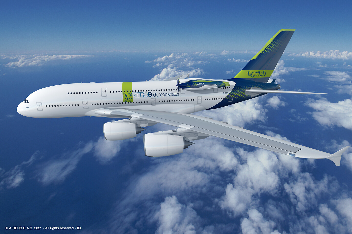
First announced publicly on 30th November this year at the Airbus Summit, the demonstrator will use Airbus’ multi-modal flight test platform – the iconic A380 MSN001. The aircraft will be modified externally to carry the fuel-cell engine pod, while inside the aircraft’s rear fuselage Airbus will install a unique cryogenic tank to contain the liquefied hydrogen.
How it works
For this proof-of-concept demonstrator, liquid hydrogen from the cryogenic tank is converted into a gaseous state. It is then distributed to the fuel cell via supply lines running from the tank and through an external ‘stub’ aerodynamic and load-bearing support structure to the engine pylon interface.
From there the gaseous hydrogen enters the fuel cell inside the pod, where dioxygen (O2) molecules are also supplied by a controlled flow of air – taken from the surrounding atmosphere. The resulting reaction inside the fuel cell produces direct electrical current (DC) which is subsequently converted into alternating current (AC) by the means of inverters. Electric motors near the front of the pod then convert the electrical power into mechanical power by communicating torque to a reduction gearbox. At the end of the propulsion chain the propeller provides the thrust. The thermal energy generated by the fuel cell needs to be conveyed by a liquid cooling system to heat exchangers where it is dissipated into the ambient air. Water is also produced as a byproduct of the electrochemical reaction which is expelled from an outlet at the back of the pod.
Modifying the A380
The A380 was the obvious choice as ‘host’ for the hydrogen fuel-cell engine demonstrator. “It has plenty of space internally – so there are no constraints in terms of accommodating everything we need, as well as the ability to test multiple configurations,” says Mathias Andriamisaina, Head of ZEROe Demonstrators and Tests at Airbus.
“In terms of aerodynamics, the A380 is a very stable aircraft. So the pod attached to the rear fuselage via the stub doesn’t pose much of an issue. Furthermore, the airflows from the pod and its propeller do not affect the airflow over A380’s tail surfaces,” he adds.
“With the A380 we also have an aircraft that’s already fully instrumented. The flight-test-instrumentation (FTI) is a big part of the project and can be a big driver in terms of cost and planning. So MSN001 was the perfect fit for us.”
The overall concept which the teams settled on was to make the minimum amount of structural modification inside the A380. “We are just reinforcing two frames of the fuselage and then fitting this stub externally. Then we are fitting a specially adapted pylon to attach the structure of the pod onto this stub. Overall it will be able to support high sustained static and dynamic loads,” he notes.
While most of the equipment is installed outside the aircraft, inside the aircraft there is what the team refers to as the “tent” – a 10m long, 4m wide housing with a parabolic cross-section, which will be crafted out of carbon fibre by an Airbus Atlantic team at the Technocentre de Nantes. Inside this structure can be housed up to four cryogenic tanks containing the liquid hydrogen. During flight tests, the actual air inside the tent will be at the same pressure as outside the aircraft. In other words, the equipment installed inside this tent will only ‘see’ the atmospheric unpressurised environment. This includes the hydrogen supply lines from the tank, which is routed directly from the tent to the stub (also made in Nantes) and then to the externally mounted pod (to be assembled at Airbus’ factory in St Eloi in Toulouse).
“Using this approach avoids the risk of any hydrogen entering into the A380’s main pressurised interior because all the hydrogen routings from the tank will also be located inside our protective tent environment. There are also emergency venting lines, so we can expel the hydrogen out of this emergency line if needed,” explains Mathias.
Other Airbus ‘firsts’
“Everything concerning the distribution centre and the motor controller unit are being produced internally – this is an ‘Airbus’ activity,” enthuses Mathias. “In addition, the propelling system and the gearbox associated and the pitch control is developed by our own Airbus Helicopters and Defence and Space colleagues. It’s the first time that Airbus is creating such an engine ourselves – it’s a big challenge.”
Other firsts for Airbus’ include the adoption of a high-voltage distributed electrical architecture for up to 1,000 Volts DC and also the creation of a bespoke engine control system – this will translate the thrust commanded by the crew into the actual shaft power.
Next steps
Extensive ground testing activities are already well underway. Examples include the electrical benches, thermal management systems and several fuel-cell integration benches. From 2024 there will be additional integrated test benches such as: a fuel cell system integration bench featuring a 200kW fuel-cell stack and a climatic chamber; a functional integration bench (FIB) for the engine control system to validate real interfaces and actuators; and a Propeller Integration Bench (PIB). The latter will explore propeller pitch actuation gearbox integration, gearbox endurance, and partial blade-release tests.
In parallel, the newly developed power centres and power converters for the fuel cell flight demonstrator will be connected to the A380 “iron bird” test rig so as to integrate them with the legacy A380 ATA Chapter 24 hardware (electrical power).
Later that year there will also be an “iron pod”. This test rig will bring together for the first time various key ingredients: 800kW of fuel cell power to two electric motors; the motor control units; the gearbox; the new high-voltage electrical distribution and conversion system; a ‘flight’ air supply and the liquid cooling system.
By 2026, and all being well following the various integration bench tests, the teams will be able to test the entire system in the integrated test bench (ITB). This will comprise the flight-standard fuel cell pod, complete with all its various systems and of course the propeller. The ITB, which will be built in 2024, will be connected to the same flight test instrumentation as for the A380 MSN001 and there will also be a co-located control room for flight crew training.
“Between now and the flight tests in 2026 we have a lot of challenges ahead, not only in design for sure, but also in the testing!” declares Mathias.

